[vc_row css=”.vc_custom_1486564869799{margin-top: 40px !important;margin-bottom: 30px !important;}”][vc_column width=”2/3″ offset=”vc_col-lg-offset-2 vc_col-lg-8″][nm_button title=”<<< Back to the product page” style=”filled_rounded” link=”url:http%3A%2F%2Fwww.bumblebeepro.com%2Fshop%2Fbb-d1-jfet-active-direct-box-diy-kit%2F|||”][/vc_column][/vc_row][vc_row css=”.vc_custom_1486563981974{margin-bottom: 40px !important;}”][vc_column width=”2/3″ offset=”vc_col-lg-offset-2 vc_col-lg-8″][vc_column_text]
Bb-D1 Active Direct Box DIY Kit Assembly Manual
Illustrated step-by-step guide to the assembly process of Bb-D1 Active J-Fet DI DIY Kit.
Published: 2015.04.24, last updated: 2017.02.08. Author: Artur Fisher.
Introduction
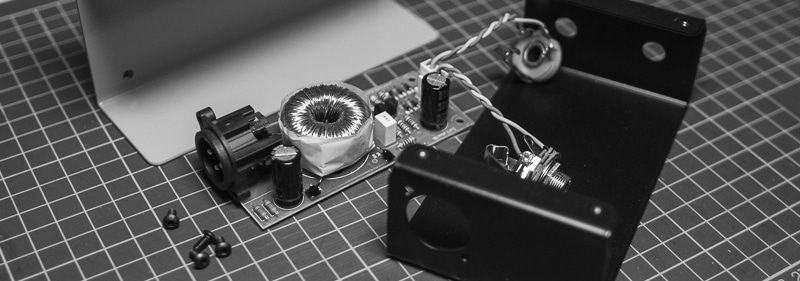
Dear DIY audio fellows, I have written this manual in order to make the Bb-D1 Active DI Kit assembly process as easy as possible, even for total beginners. I hope that the illustrations will help you to understand each step clearly and that the whole assembly process is flawless and enjoyable!
If anything is unclear, please contact me on info@diyaudiocomponents.com and I will provide the assistance ASAP.
All the best!
Artur Fisher.
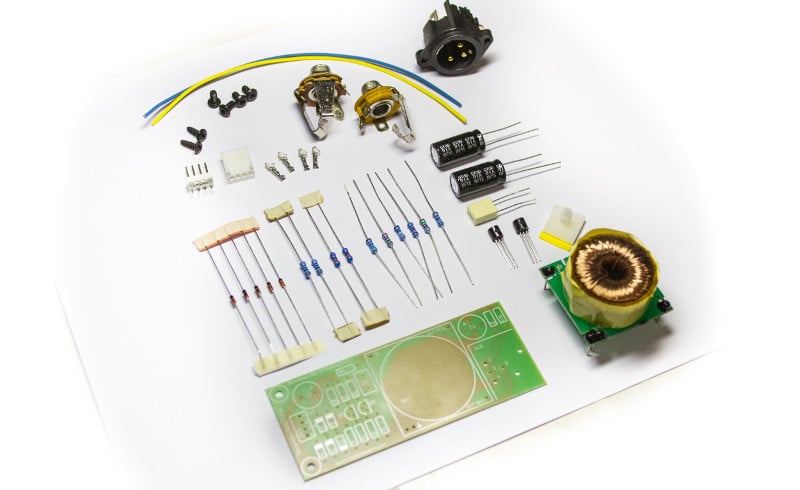
1. What’s In The Box
What’s in the box:
- All the electronic parts – resistors, capacitors, zener diodes
- Cherry-picked 2SK246 j-fet and BC547C transistor
- Leads for wiring the jack plugs
- Custom designed toroidal output transformer
- PCB (Printed Circuit Board)
- All the connectors – input and output jacks, output XLR, molex-type plug with pins
- Self-adhesive PCB holder
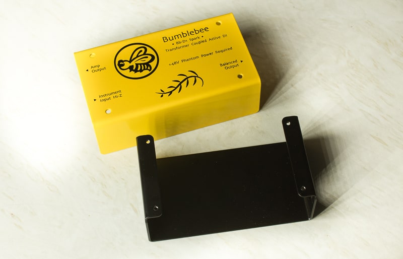
- Pre-drilled and punched, powder coated and silkscreened enclosure with all the screws
What else is required:
- Soldering iron
- Some solder
- Digital multimeter for sorting the resistors and testing the continuity
- 5/64 Hex Wrench (Allen Key) or screwdriver with 5/64 hex head.
- Small philips screwdriver.
- Lineman’s pliers (or other type of pliers)
- A small piece of wire for a jumper
- Some sandpaper for removing the powder coating
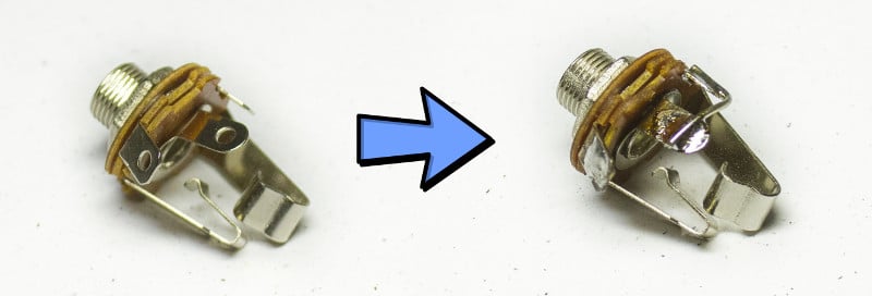
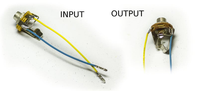
2. Solder the jumpers on jack sockets
Solder the jumpers on jack sockets as shown on pictures below. These jumpers are necessary for proper grounding. You can use any piece of wire or a remaining lead from the resistor or any other component. Please note that the top picture shows the input jack and the bottom picture shows the output jack – don’t mix them up, you will have to determine which is which later on.

3. Prepare the wires and solder the pins on
Now the wires have to be prepared. Cut the included wires in halves, strip and tin the ends. Solder the Molex plug pins on one end of each wire, as show on picture below. Soldering the pins sometimes causes confusions, but there is nothing complicated about it. You can fix the tip of the pin in a small wise or in lineman’s pliers (the weight of pliers will be enough to hold the pin, so both of your hands will be free for soldering), then simply solder the wire and slightly bend the sides of the pin inside, so it fits the body of the plug. That’s it.

4. Solder the wires to the jack sockets
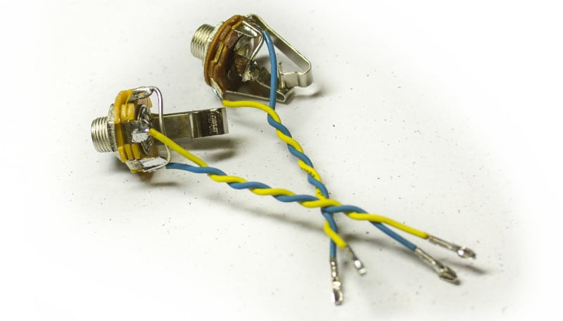
Solder the free (unpinned) ends of the wires to the jack sockets. Note that the wire color order is essential, solder exactly as shown on picture below!
5. Twist the wires
Twist the wires tightly and evenly.
6. Insert the pins of the output jack into the plug
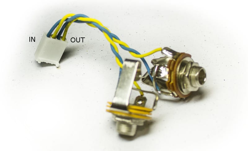
Insert the pins of the output jack into the body of the Molex plug. Note the orientation of the pin while inserting (shown on picture below, left side). Note the color order of the wires in the Molex plug (shown on picture below, right side).

7. Insert the pins of the input jack into the plug
Now insert the pins of the input jack into the body of the Molex plug. The wire color order is the same as for the output jack socket that went first (see the picture below).
8. Solder the zener diodes on the PCB
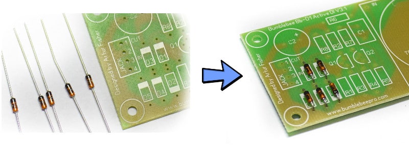
Finally we’ve got to PCB soldering. I know, nobody likes wiring! OK, now solder the zeners on the PCB. Note that zener diodes are polarized! The black band on the body of a diode should align with the white band on the PCB marking (see the picture below, right side). Pay attention to the D2 zener diode – it has the opposite orientation on the PCB relative to the rest of diodes! Diodes are heat-sensitive, so when all of them are inserted and ready to solder, I advice to solder one lead of each diode first and then the other leads, so there is a time for the diodes to cool down. All the zeners are of the same type, so there is no need to sort them.
9. Sort and solder the resistors on the PCB
Now it’s time for some sorting. Use the multimeter to measure the resistor values and place them on PCB accordingly. Resistor numbers are marked on the PCB (visible on the picture above, right side). Resistors are not polarized, so their orientation is not essential.
Resistor values:
- R1 – 10 MOhms. Some multimeters can only measure up to 1 MOhm, in such case it will be the only resistor you can’t get reading for. R1 sets the input impedance of the device.
- R2 – 1.5 KOhms. This is a drain load resistor of the j-fet
- R3 – 390/430/470 Ohms. This is a source resistor of the j-fet. R3 sets the working current of the j-fet and can be 390, 430 or 470 Ohms, depending on the specs of the particular j-fet (Q1). Q1/R3 pairs come matched with every kit! So, when you see any of those three values, you’ve got R3.
- R4 – 100 Ohms. This is a base-stopper that prevents the possible instability of the emitter follower (Q2).
- R5 – 5.6 KOhms. This resistor sets the working current of the emitter-follower (Q2).
- R6 – 220 Ohms. R6 and C2 form the second stage of the power supply filter.
- R7 – 100 Ohms. The resistor that isolates the emitter follower output from the load, required for stability.
- R8 – 10 KOhms. Amp output isolation resistor.
- R9, R10 – 3.3 KOhms, matched to 0.1%. Phantom power filter resistors.
- R9, R10 and C3 form the first stage of the power supply filter.
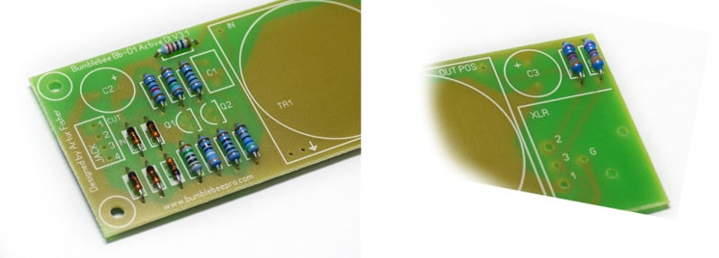
10. Solder the transistors on the PCB
There are two transistors in the circuit – 2SK246BL j-fet and BC547C bipolar. These part numbers can be found on the flat sides of transistors. The j-fet works as an input stage with high input impedance, the bipolar works as emitter follower (current amplifier) that reduces the output impedance for very efficient output transformer drive. Obviously, the transistors are polarized! Both transistors must be installed with their rounded sides aligned with the rounded lines on PCB marking. Transistors are heat-sensitive, so solder with care and don’t allow overheating!
Transistor types:
Q1 – 2SK246BL. The j-fets are know for the very wide parameter variations, so every unit must be tested and sorted. This hard work is done for you, because every kit comes with the hand selected 2SK247BL and its matching source resistor R3.
Q2 – BC547C. This transistor acts as a transformer driver in this circuit.
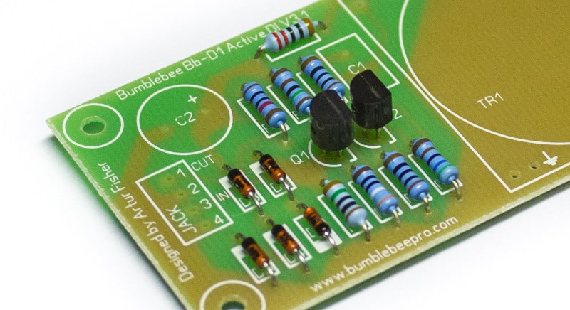
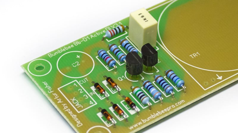
11. Solder the film capacitor on the PCB
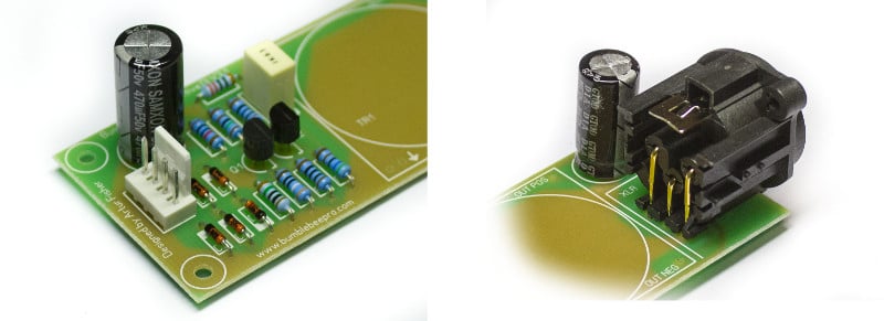
The film capacitor C1 is the rectangular one (see the picture below). Film capacitors are not polarized, so its orientation is not essential. This capacitor functions as a DC blocking capacitor in this circuit. It isolates the output transformer from the DC, but passes the AC (your audio signal) through.
12. Solder the electrolytic capacitors on the PCB
Solder both electrolytic capacitors on the PCB. They have the same value, so there is no need for sorting. Electrolytic capacitors are polarized! See the picture below for the correct “minus” side orientation.
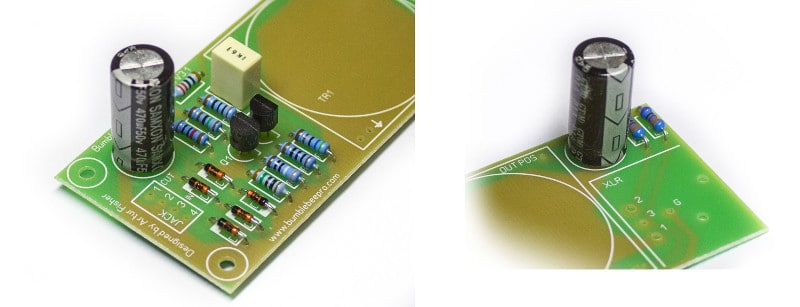
13. Solder the Molex and XLR plugs on the PCB
Solder the male Molex plug on the PCB. See the picture below (left side) for the correct orientation. Solder the XLR plug. It is not possible to place it the wrong way, so no stress here.
14. Solder the output transformer on the PCB
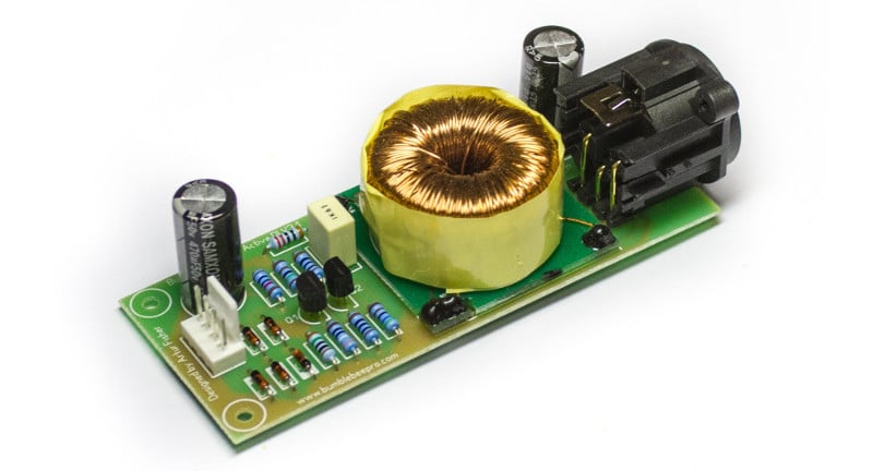
Solder the output transformer on the PCB. It is supplied fixed on a pad with pins. There are two pins in one corner for proper orientation, so it is not possible to place the transformer the wrong way. There is one flying lead that comes out of the coil. It is the end of the Faraday shield, it should not be connected anywhere! Just cut it off around 10 mm away from the transformer.
You’ve got the fully assembled circuit board of the DI now!
I would advice to test the device before proceeding to the assembly in the enclosure! Connect your pre-wired jack sockets to the PCB, connect the XLR output to the microphone input of your console/preamp/interface, plug the instrument (or other signal source) into the input jack, switch the phantom power on and rock. After making sure that it sounds you can confidently proceed to assembling everything in the enclosure.
15. Insert the jack sockets into the enclosure
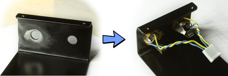
First, the proper grounding. Use the sandpaper to remove the paint around the input jack opening, the left one looking from inside (see the picture below, left side). Now insert the jack sockets – input jack to the left, output jack to the right, looking from inside (see the picture below, right side). Check if the input jack is in proper contact with the chassis – set the multimeter in continuity mode and test any metal part of the input jack against the inside of the threaded screw holes (on the top). You should have a stable continuity. If there is no continuity, remove more paint around until it tests OK.
16. Insert the circuit board into the chassis.
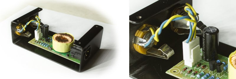
Insert the circuit board into the chassis and fix the XLR socket with two self-tapping screws (see the picture below). Follow the general rule of thumb for the self-tapping screws – when you are working them in, do one full turn forward then half-turn back all the way. Don’t tighten the screws to strongly as you can damage the thread in the plastic.

17. Insert the self-adhesive PCB holder
Remove the protective film from the PCB holder, lift the PCB carefully and place the holder underneath it, so it is aligned with the mounting hole on the PCB. Carefully let the PCB in place and when you are sure that the holder is aligned properly, push the corner of the PCB down and the holder will clip into the mounting hole.

18. Connect the jack sockets to the PCB
Connect the jack socket female Molex plug to the male Molex plug on the PCB. Make sure it clicks. Just a little more patience, you are almost done!
19. Remove some paint around the screw hole
Remove some paint around the screw hole on enclosure cover. It can be any of four holes. It is necessary for proper grounding – this way the top of the enclosure will be in contact with the chassis via the screw. I have found that the most convenient way is to use a large or medium size philips screwdriver for this purpose – simply insert it in the hole and rotate.

20. Fasten the screws and rock!
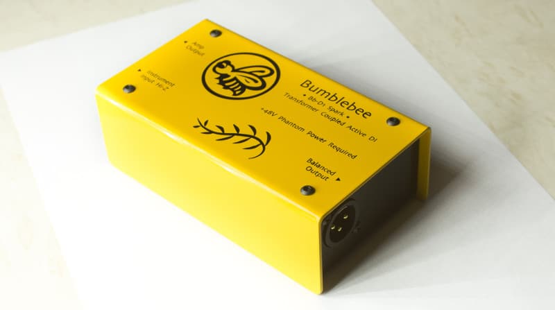
Fasten all the remaining screws, connect your DI and rock-n-roll! Don’t fasten the screws too tightly in order not to damage the thread. Congrats with assembling your Active Direct Inject Box!
 [/vc_column_text][/vc_column][/vc_row][vc_row css=”.vc_custom_1486550441018{margin-bottom: 50px !important;}”][vc_column width=”1/3″ offset=”vc_col-lg-offset-4 vc_col-lg-4″][vc_column_text]
Order Now:
[/vc_column_text]
€129.00 excl. VATRead more
[/vc_column][/vc_row]